
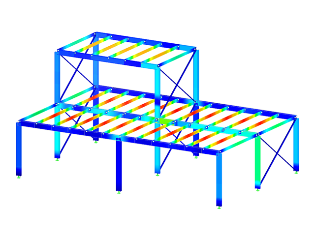
The modal relevance factor (MRF) can help you to assess to which extent specific elements participate in a specific mode shape. The calculation is based on the relative elastic deformation energy of each individual member.
The MRF can be used to distinguish between local and global mode shapes. If multiple individual members show significant MRF (for example, > 20%), the instability of the entire structure or a substructure is very likely. On the other hand, if the sum of all MRFs for an eigenmode is around 100%, a local stability phenomenon (for example, buckling of a single bar) can be expected.
Furthermore, the MRF can be used to determine critical loads and equivalent buckling lengths of certain members (for example, for stability design). Mode shapes for which a specific member has small MRF values (for example, < 20%) can be neglected in this context.
The MRF is displayed by mode shape in the result table under Stability Analysis → Results by Members → Effective Lengths and Critical Loads.

Several modeling tools are available for elements in building models:
- Vertical line
- Column
- Wall
- Beam
- Rectangular floor
- Polygonal floor
- Rectangular floor opening
- Polygonal floor opening
This feature allows you to define the element on the ground plane (for example, with a background layer) with the associated multiple element creation in space.

In the Steel Joints add-on, you can determine the initial stiffness Sj,ini according to Eurocode and AISC. This can be done for selected members with reference to the internal forces N, My, and Mz.
In the Members tab of the input dialog box of the Steel Joints add-on, you can select the desired internal forces via a checkbox. Multiple selection is possible. For these internal forces, the stiffness analysis is carried out with a positive and a negative sign.
Go to Explanatory Video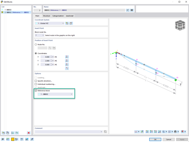
When using multiple identical blocks in a model, you can assign a reference block to the selected blocks.
If you then change parameters such as geometry, material, and cross-section of the reference block, these are automatically adopted for the "child blocks".
Go to Explanatory Video
The "Member Editor" component allows you to modify the individual or several member plates in the Steel Joints add-on.
You can use the chamfer, notch, rounding, and hole operations with multiple shapes. It is possible to apply both operations, "Notch" and "Chamfer", for several member plates.
In this way, you can notch flanges from I-sections, for example (see the image).
Go to Explanatory Video
Utilize this time-saving step! This feature allows you to define or edit the member reinforcement for several members or member sets at the same time.
Go to Explanatory Video
- For a new connection model, you have to select a node in the RFEM model
- After selecting a node, the members connected to the node are automatically recognized and assigned
- In the window for assigning members, select the ones that will be assigned to the connection
- The members marked by us are displayed in the preview window on the right
- Connections can be modeled for multiple nodes in a structure.
- For member settings, select the ones to be supported
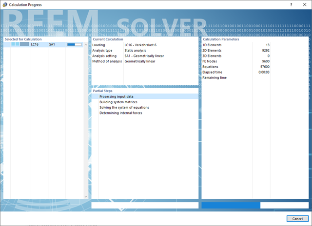
Do you have to calculate multiple load combinations in your models? Then several solvers (one per core) are initiated in parallel, each of which calculates a load combination. This ensures a better utilization of the cores and thus faster calculations.
Go to Explanatory Video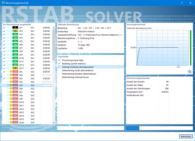
Also in this case, RSTAB will certainly convince you. With the powerful calculation kernel, its optimized networking and support of multi-core processor technology, the Dlubal structural analysis program is far ahead. This allows you to calculate more linear load cases and load combinations using several processors in parallel without using additional memory. The stiffness matrix only has to be created once. Thus, it is possible for you to calculate even large systems with the fast and direct solver.
Do you have to calculate multiple load combinations in your models? The program initiates several solvers in parallel (one per core). Each solver then calculates a load combination for you. This leads to better utilization of the cores.
You can systematically follow the development of the deformation displayed in a diagram during the calculation, and thus precisely evaluate the convergence behavior.
Convince yourself by the powerful calculation kernel, its optimized networking and support of multi-core processor technology. This provides you with the advantages, such as parallel calculations of linear load cases and load combinations using several processors without additional demands on the RAM. The stiffness matrix only has to be created once. Thus, you can calculate even large systems with the fast direct solver.
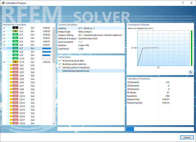
If you need to calculate multiple load combinations in your models, the program initiates several solvers in parallel (one per core). Each solver then calculates a load combination, which improves the core utilization.
You can systematically follow the development of the deformation displayed in a diagram during the calculation, and thus precisely evaluate the convergence behavior.
- General stress analysis
- Automatic import of internal forces from RFEM/RSTAB
- Complete graphical and numerical results of stresses and stress ratios integrated in RFEM/RSTAB
- Wide range of customization options for graphical output
- Flexible design in multiple design cases
- Clearly arranged result tables for a quick overview after the design
- High productivity due to the minimal amount of input data required
- Flexibility due to detailed setting options for basis and extent of calculations
- Design of the following column types:
- Hinged column, optionally with elastic restraint of head or footing
- Bracket, optionally with elastic restraint of footing
- Simple geometry input with illustrative graphics
- Extensive material library
- Allocation of framework to service classes and specification of service class categories
- Detailed settings of the fire resistance design
- Specification of limit deformation for the serviceability limit state design
- Determination of design ratios, support forces, and deformations
- For design according to EC 5 (EN 1995), the following National Annexes are available:
-
 DIN EN 1995-1-1/NA:2013-08 (Germany)
 -
 NBN EN 1995-1-1/ANB:2012-07 (Belgium)
 -
 DK EN 1995-1-1/NA:2011-12 (Denmark)
 -
 SFS EN 1995-1-1/NA:2007-11 (Finland)
 -
 NF EN 1995-1-1/NA:2010-05 (France)
 -
 UNI EN 1995-1-1/NA:2010-09 (Italy)
 -
 NEN EN 1995-1-1/NB:2007-11 (Netherlands)
 -
 ÖNORM B 1995-1-1:2015-06 (Austria)
 -
 PN EN 1995-1-1/NA:2010-09 (Poland)
 -
 SS EN 1995-1-1 (Sweden)
 -
 STN EN 1995-1-1/NA:2008-12 (Slovakia)
 -
 SIST EN 1995-1-1/A101:2006-03 (Slovenia)
 -
 CSN EN 1995-1-1:2007-09 (Czech Republic)
 -
 BS EN 1995-1-1/NA:2009-10 (the United Kingdom)
 - Automatic generation of wind and snow loads
- Multiple optional reductions according to the selected standard
- Direct data export to MS Excel
- Program languages: English, German, Czech, Italian, Spanish, French, Portuguese, Polish, Chinese, Dutch, and Russian
- Verifiable printout report, including all required designs. Printout report available in many output languages; for example, English, German, French, Italian, Spanish, Russian, Czech, Polish, Portuguese, Chinese, and Dutch.
- Direct import of stp files from various CAD programs
- Design of the following geometrical types:
- Single-span beams with and without cantilevers
- Continuous beams with and without cantilevers
- Hinged girder system (Gerber beams) with and without cantilevers
- For design according to EC 5 (EN 1995), the following National Annexes are available:
-
DIN EN 1995-1-1/NA:2013-08 (Germany)
-
NBN EN 1995-1-1/ANB:2012-07 (Belgium)
-
DK EN 1995-1-1/NA:2011-12 (Denmark)
-
SFS EN 1995-1-1/NA:2007-11 (Finland)
-
NF EN 1995-1-1/NA:2010-05 (France)
-
UNI EN 1995-1-1/NA:2010-09 (Italy)
-
NEN EN 1995-1-1/NB:2007-11 (Netherlands)
-
ÖNORM B 1995-1-1:2015-06 (Austria)
-
PN EN 1995-1-1/NA:2010-09 (Poland)
-
SS EN 1995-1-1 (Sweden)
-
STN EN 1995-1-1/NA:2008-12 (Slovakia)
-
SIST EN 1995-1-1/A101:2006-03 (Slovenia)
-
CSN EN 1995-1-1:2007-09 (Czech Republic)
-
BS EN 1995-1-1/NA:2009-10 (the United Kingdom)
-
- Automatic generation of wind and snow loads
- Multiple optional reductions according to the selected standard
- Simple geometry input with illustrative graphics
- Free entry of tapered geometries. Free selection of the grain angle allows for user-defined design of the compressive and tensile areas for bending
- Comprehensive and extensible material library
- Determination of design ratios, support forces, and deformations
- Color reference scales in result tables
- Direct data export to MS Excel
- DXF interface for preparation production documents in CAD
- Program languages: English, German, Czech, Italian, Spanish, French, Portuguese, Polish, Chinese, Dutch, and Russian
- Verifiable printout report, including all required designs. Printout report available in many output languages; for example, English, German, French, Italian, Spanish, Russian, Czech, Polish, Portuguese, Chinese, and Dutch.
- Direct import of stp files from various CAD programs